量子电路基础使用
量子电路 (Circuit) 是 QuICT 中最为基础的模块,无论是量子算法,还是优化映射,都需要构建相对应的量子电路。本文将介绍如何使用 QuICT 构建我们所需要的量子电路,以及如何按照需求进行电路优化,编译或者仿真模拟。
构建量子电路
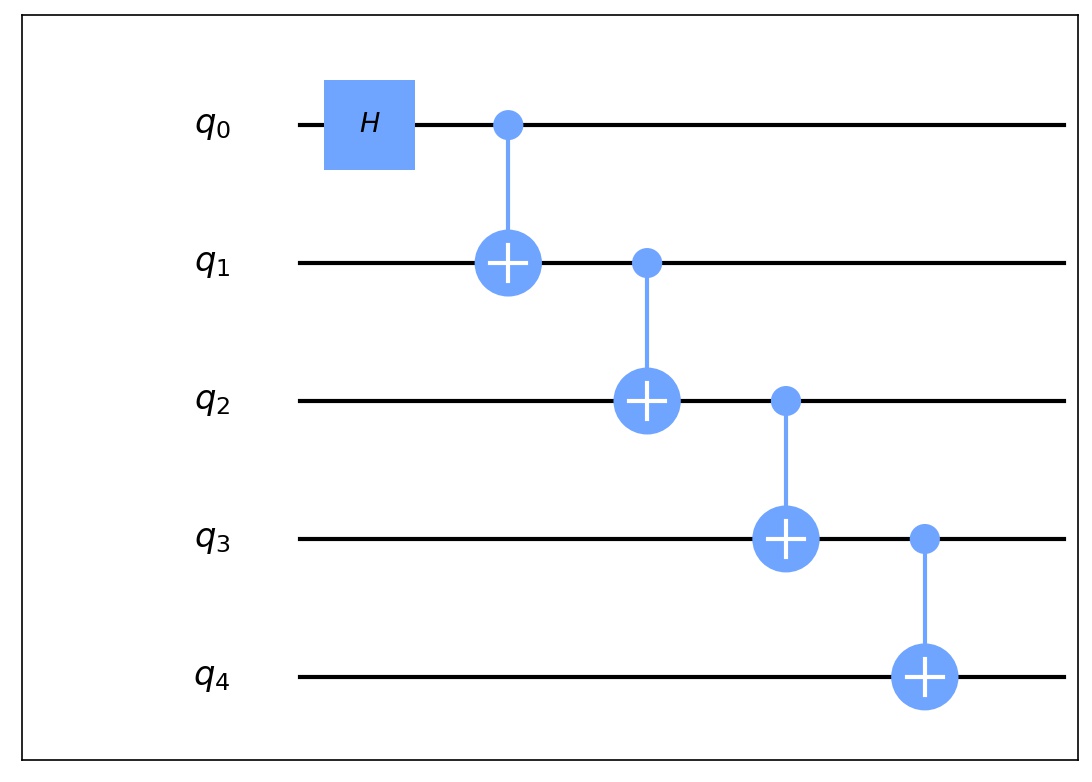
构建量子电路是整个量子计算中最为重要的一部分,量子电路是由量子比特和量子门组成的,通过将量子比特和量子门进行特定组合可以实现所需要的功能。下面是如何构建一个GHZ态量子电路。
from QuICT.core import Circuit
from QuICT.core.gate import H, CX

# 构建 5 比特GHZ态量子电路
circuit = Circuit(5)
H | circuit(0)
CX | circuit([0, 1])
CX | circuit([1, 2])
CX | circuit([2, 3])
CX | circuit([3, 4])
如何使用组合量子门
组合量子门也可以被加入到量子电路中,作为量子电路的一部分。通过构建组合量子门可以大大简化量子电路的构建难度,也可以提高代码的复用性。
from QuICT.core import Circuit
from QuICT.core.gate import CompositeGate, H, CX

# 构建组合量子门
cg = CompositeGate()
CX | cg([0, 1])
CX | cg([1, 2])

# 构建 5 比特GHZ态量子电路
circuit = Circuit(5)
H | circuit(0)
cg | circuit([0, 1, 2])
cg | circuit([2, 3, 4])
动态量子电路
QuICT 构建了 Trigger 类,来支持量子电路的动态构建。与普通量子门不同的是, Trigger 类支持根据当前状态下的量子比特测量结果,运行不同的量子电路。
from QuICT.core import Circuit
from QuICT.core.gate import CompositeGate, H, CX
from QuICT.core.operator import Trigger

cir = Circuit(3)
H | cir(0)
CX | cir([0, 1])

# 构建组合量子门,测试用示例
cgate0 = CompositeGate()
CX | cgate0([0, 1])
cgate1 = CompositeGate()
CX | cgate1([1, 0])

# 构建 Trigger
state_mapping = {
    0: cgate0,      # 当量子比特测量值为0时,执行的电路
    1: cgate1       # 当量子比特测量值为1时,执行的电路
}

trigger = Trigger(
    targets=1,      # 量子比特数量
    state_gate_mapping=state_mapping    # 量子比特测量结果所对应的量子电路或者量子门
)

trigger | cir(1)
# 目标比特测量值为0的模拟结果
[1.+0.j 0.+0.j 0.+0.j 0.+0.j 0.+0.j 0.+0.j 0.+0.j 0.+0.j]

# 目标比特测量值为1的模拟结果
[0.+0.j 0.+0.j 1.+0.j 0.+0.j 0.+0.j 0.+0.j 0.+0.j 0.+0.j]
如何调整已构建好的量子电路
QuICT 中的量子电路 Circuit 实现了 insert、pop、split 和 sub_circuit 等多种操作
from QuICT.core import Circuit

# 构建5比特量子电路
cir = Circuit(4)
cir.random_append(20)

# 额外插入量子门到指定位置
cir.insert(CX & [0, 2], 11)  # insert the CX Gate into the 11th index.
cir.insert_by_position(Rxx, [0, 3], 4)  # Insert the Rxx Gate with qubits 0, 3 and depth 4

# 取出指定位置的量子门
_ = cir.pop_by_position([1], 2)     # Pop the gate with qubits 1 and depth 2
_ = cir.pop(0)  # pop the first gate from circuit
量子电路转换
量子电路的矩阵表示
对于每一个量子电路,都可以由一个 \(2^n \times 2^n\) 的酉矩阵所表示。
[[0.70710678+0.j 0.        +0.j 0.        +0.j ... 0.        +0.j
  0.        +0.j 0.        +0.j]
 [0.        +0.j 0.70710678+0.j 0.        +0.j ... 0.        +0.j
  0.        +0.j 0.        +0.j]
 [0.        +0.j 0.        +0.j 0.        +0.j ... 0.        +0.j
  0.        +0.j 0.        +0.j]
 ...
 [0.        +0.j 0.        +0.j 0.        +0.j ... 0.        +0.j
  0.        +0.j 0.        +0.j]
 [0.        +0.j 0.70710678+0.j 0.        +0.j ... 0.        +0.j
  0.        +0.j 0.        +0.j]
 [0.70710678+0.j 0.        +0.j 0.        +0.j ... 0.        +0.j
  0.        +0.j 0.        +0.j]]
量子电路与 OPENQASM
QuICT 支持与 OPENQASM 之间的相互转换。
Note
目前暂不支持 Unitary 门的 OPENQASM 转换。
from QuICT.tools.interface import OPENQASMInterface

# 将 QASM 文件转换为 Circuit
qasm_circuit = OPENQASMInterface.load_file("/path/to/qasm/file").circuit

# 将 Circuit 转换为 QASM
qasm_circuit.qasm(output_file="/path/to/store/qasm/file")
量子电路的有向无环图表示
QuICT 中支持将量子电路根据其中量子门的可交换性转换为有向无环图表示,便于后续的电路优化和编译。
量子电路可视化
QuICT 支持量子电路可视化,可以通过 Circuit.draw() 实现。
量子电路自动化设计
QuICT 内置了多种量子电路编译和优化算法,可将任意量子电路编译到指定量子计算机可运行的格式;另一方面,也可以支持对构建好的量子电路在保证等价性的前提下,进行进一步的优化。
from QuICT.core.virtual_machine.quantum_machine import OriginalKFC6130
from QuICT.qcda import QCDA

circuit = Circuit(4)
circuit.random_append(10, random_params=True)

qcda = QCDA()
circuit_phy = qcda.auto_compile(circuit, OriginalKFC6130)

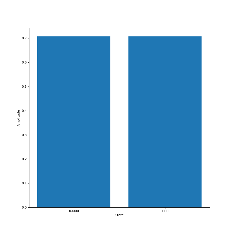
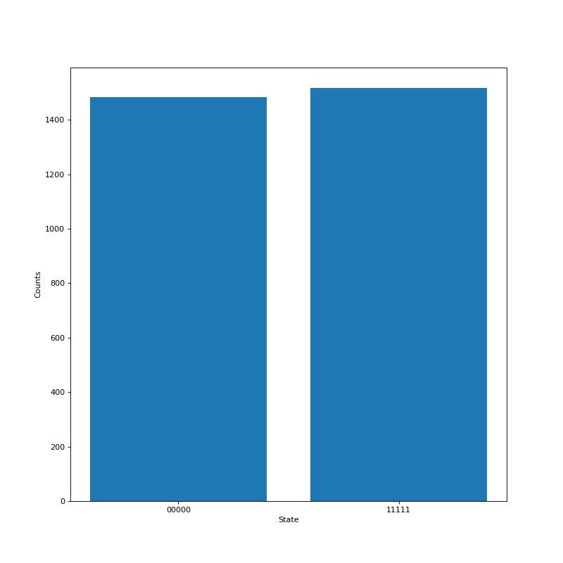
量子电路仿真模拟
QuICT 通过使用 Simulator 来进行量子电路模拟,目前实现了三种模拟器。模拟器支持量子电路和初始状态向量作为输入,输出经过量子电路之后的状态向量,通常为一个 \(2^n\) 的复数向量,如果模拟器选择使用密度矩阵模拟器,输出则会是密度矩阵,为一个 \(2^n \times 2^n\) 的复数矩阵。
from QuICT.simulation.state_vector import StateVectorSimulator
from QuICT.tools.display import sample_drawer, amplitude_drawer


# 使用上方构建的 5 比特GHZ态量子电路
circuit = ...

# 使用状态向量模拟器来进行量子电路模拟
simulator = StateVectorSimulator()
state_vector = simulator.run(circuit)
amplitude_drawer(state_vector)
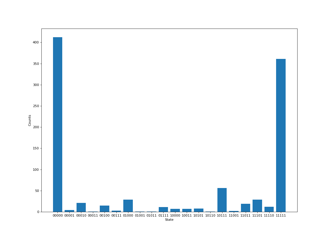
含噪声量子电路模拟
QuICT 可通过在模拟过程中,输入物理机模型或噪声模型来进行含噪声仿真模拟。 ``
from QuICT.core.virtual_machine.quantum_machine import OriginalKFC6130
from QuICT.tools.display import sample_drawer

simulator = StateVectorSimulator()
state_vector = simulator.run(circuit, quantum_machine_model=OriginalKFC6130)
sample = simulator.sample(1000)
sample_drawer(sample)